Boiler tubes are essential components in industrial steam systems, where continuous high-temperature and high-pressure conditions demand exceptional material performance. This blog highlights a recent metallurgical investigation performed on a ruptured steel boiler tube. The findings reveal how long-term exposure to heat, pressure, and oxidation can lead to catastrophic failure.
1. Visual Examination
The received boiler tube exhibited a distinctive ‘fish-mouth’ rupture — a hallmark of stress rupture failure. Externally, a thick oxide layer was observed, along with a characteristic rectangular ‘crocodile skin’ pattern. This pattern is typically caused by thermal fatigue and fireside corrosion. The oxide scale not only reduces heat transfer efficiency but also contributes to tube wall thinning over time.
(a)
(b)
(c)
(d)
(e)
(f)
(g)
Figure 1:The ruptured boiler tube section is shown in (a), (b) through (e) shows the ruptured area, the rectangles pattern, crocodile skin, and the oxide layer, (f) evidence of localized corrosion under the rectangle shaped oxides, and (g) oxide pieces removed from the exterior of the tube. The section of the 3 samples for microscopy is also shown in (a).
2. Material and Chemical Analysis
Chemical composition tests confirmed the tube to be made of low carbon steel. Trace amounts of manganese, silicon, and chromium were identified — typical for this class of steel. The oxide residues mainly contained magnetite (Fe₃O₄), indicating long-term oxidation exposure. The analysis also confirmed carbon depletion near the outer surface due to diffusion at elevated temperatures.
(a)
(b)
(c)
(d)
(e)
(f)
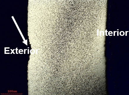
Figure 2: Optical microscope images from sample 1, as marked in Figure 1a, (a) shows the result of high temperature thinning due to corrosion and thermal fatigue, (b) oxide layer at the exterior of the tube and the resulting rough area of the tube wall under the oxide layer, (c) voids that formed in the tube due to creep are shown by arrows, (d) oxide layer at the interior of the tube, (e) microstructural changes at the area near extremely hot exterior surface of the tube because of diffusion as well as decarburization, (f) The microstructure of the steel tube at the core of the tube away from the exterior that is a mixture of pearlite and ferrite.
3. Microstructural Examination
Microscopic evaluation revealed a mixture of ferrite and pearlite phases, consistent with low-carbon steel. However, regions near the outer wall showed severe pearlite depletion, forming carbon-depleted ferrite zones. These areas also contained voids along grain boundaries, indicative of creep damage — a process where prolonged stress at high temperature causes microvoid formation and coalescence, eventually leading to fracture.
(a)
(b)
(c)
(d)
Figure 3: Optical microscope images taken from sample 2, (a) a composite image in as polished condition showing a through thickness fracture section at the area of localized thinning, (b) and (c) shows large size voids, as pointed to by the arrows, near the exterior of the tube that is also covered by an oxide layer, and (d) is a composite image of the etched sample that reveals threeareas of localized thinning on the exterior surface of the tube as pointed to by the arrows.
4. Failure Mechanism
The failure occurred as a result of combined mechanisms — primarily creep, thermal fatigue, and oxidation. At operating pressures around 280 psi and external gas temperatures near 1800°F, the tube wall was exposed to sustained high-temperature stress. Over time, creep-induced voids and oxidation thinning reduced the load-bearing capacity of the material, leading to final ruptu at one of the weakened, localized thinning zones.
(a)
(b)
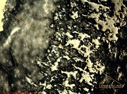
Figure 4: Microstructural changes in the tube shown here at the area of sample 2, (a) lighter color in the vicinity of the exterior of the tube, and (b) formation of more voids at the grain boundary of ferrite and coalescence of the smaller voids into larger ones leading to the final rupture.
5. Recommendations
Based on the observed failure mechanisms, several recommendations can be made to prevent similar issues in the future:
Replace current low-carbon steel tubes with creep-resistant alloys such as 2.25Cr-1Mo or stainless steel grades.
Apply protective coatings to the fireside of the tubes to minimize oxidation and thermal fatigue.
Optimize soot-blowing parameters to prevent abrupt temperature fluctuations and surface erosion.
Reduce sulfur and other corrosive elements in flue gases to minimize high-temperature corrosion.
Implement regular inspection intervals focusing on oxide scale buildup and wall thickness monitoring.
6. Conclusion
This investigation demonstrates how a combination of high-temperature oxidation, thermal fatigue, and creep can lead to stress rupture in boiler tubes. Preventive maintenance, material upgrades, and process optimization are essential to ensure the reliability and longevity of boiler components operating under extreme service conditions.
(a)
(b)
(c)
(d)
(e)
(f)
Figure 5: Optical microscope images taken from sample 3, (a) a composite image in as polished condition showing the ruptured area and an adjacent localized thinning zone, (b) a second fractured portion near the major ruptured area, (c) degraded area near the oxidized exterior, (d) shows the chemically etched sample at the ruptured area lighter color near the exterior side is due to microstructural change as well as carbon depletion, (e) is the image taken from the area of localized thinning right adjacent to the ruptured area in etched condition, and (f) shows the carbon depleted zone near the exterior similar to figure 4b.