1. Understanding Shaft Failure: A Professional Metallurgical Insight
In a recent analysis, our materials engineering laboratory investigated the failure of a short shaft compared with a reference good shaft. This investigation aimed to determine the root cause of failure and assess whether the material met specifications.
2. Background
Two short shafts were submitted — one that had failed and another that was intact. The evaluation included hardness testing, chemical composition, microscopic analysis, and advanced imaging with Scanning Electron Microscopy (SEM) and Energy Dispersive X-ray Spectroscopy (EDS).
3. Key Findings
i. Hardness Testing
Both shafts showed similar hardness values (around 46–48 HRC), suggesting that hardness alone was not the cause of failure.
ii. Chemical Composition
Chemical analysis revealed alloying elements including carbon (0.32%), chromium (1.47%), nickel (1.9%), and molybdenum (0.48%). These values are typical of steels designed for high strength applications.
iii. Microscopic Analysis
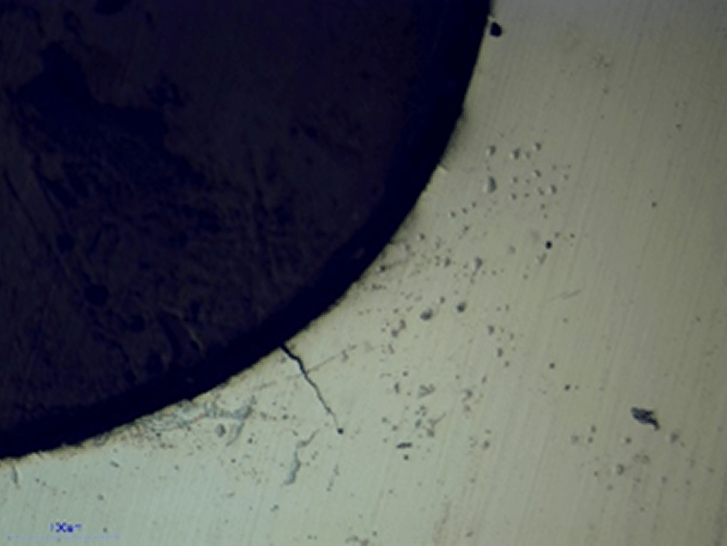
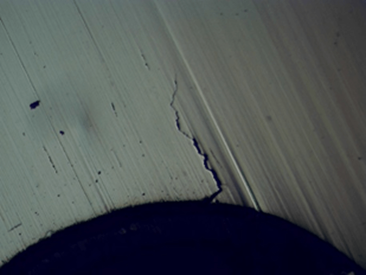
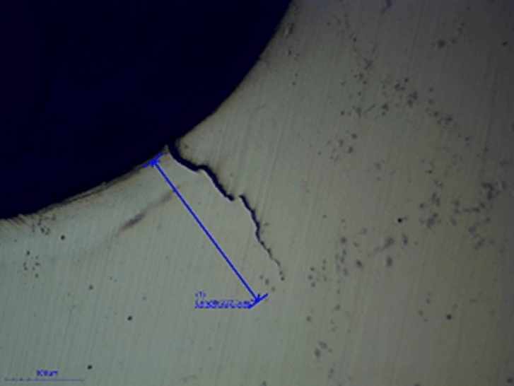
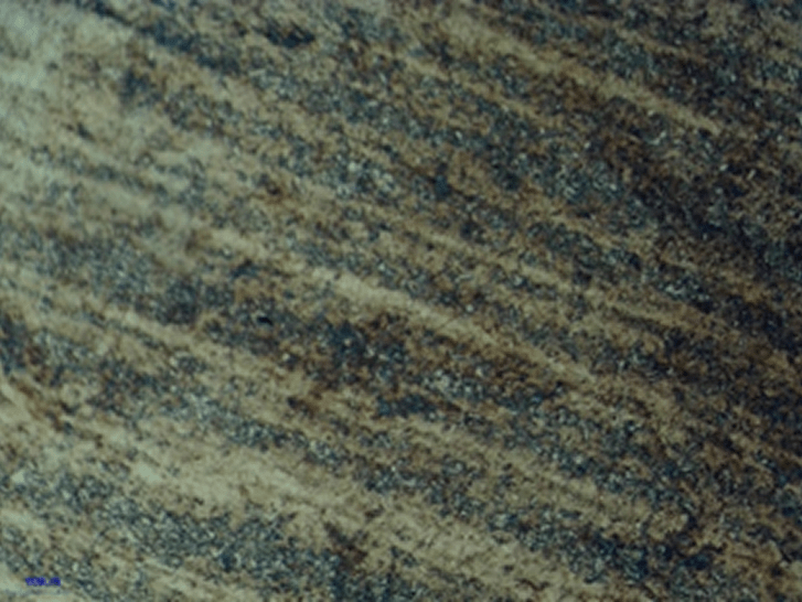
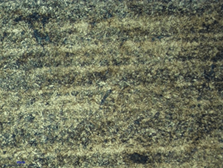
Optical microscopy revealed significant fatigue cracks at the root of the threads in the failed shaft. In contrast, the reference shaft showed no cracks. Additionally, the failed shaft exhibited strong banding in its microstructure.
iv. SEM/EDS Analysis
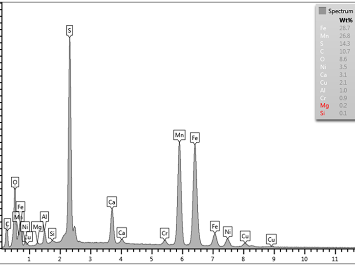
SEM confirmed fatigue as the main mode of failure. The fracture surfaces displayed rust and oxidation, which limited detailed observation. EDS detected inclusions containing manganese and sulfur — potential contributors to crack initiation.
4. Conclusion
The evidence strongly indicates that the short shaft failed due to fatigue, likely initiated at the thread roots and aggravated by environmental factors such as corrosion. While the material hardness and composition were within expected ranges, microstructural banding and inclusions increased vulnerability to fatigue. This study underscores the importance of considering service conditions, environmental exposure, and microstructural uniformity in shaft design and quality control.
Thread root cracks in the broken short shraft.
Thread roots in the reference short shaft that was not broken does not show any cracks.
Figure 1: Optical microscope images of broken and reference short shafts at 200x.
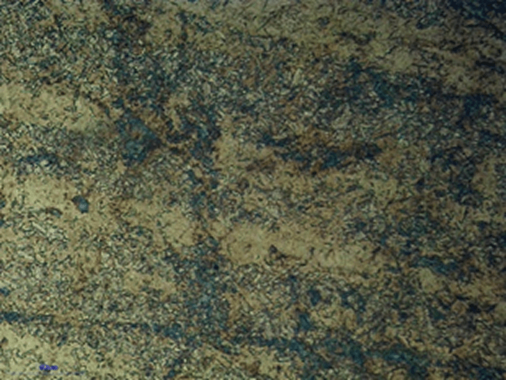
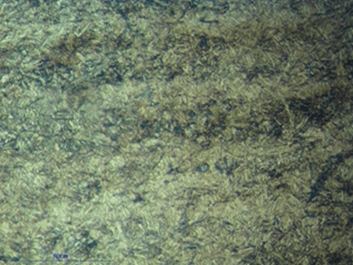
Microstructure of the failed short shaft in the vicnity of the areas with cracks.
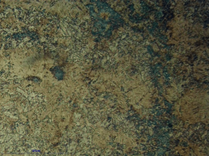
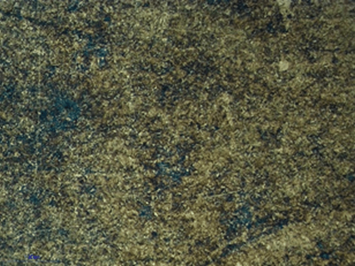
Microstructure of the failed short shaft in areas not showing any cracks.
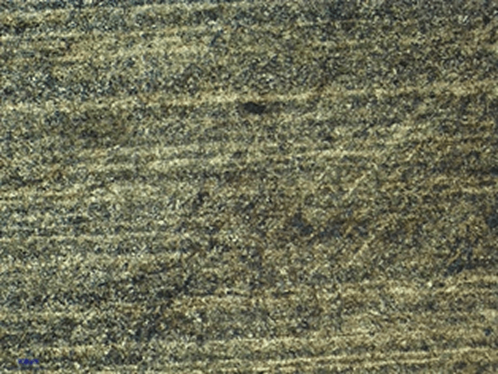
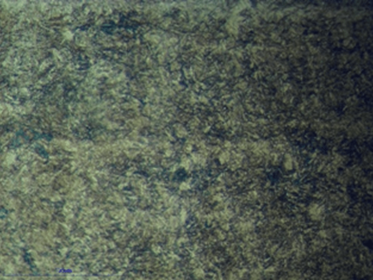
Microstructure of the reference short shaft that was not broken.
Figure 2: Microstructural features of failed and reference shafts.
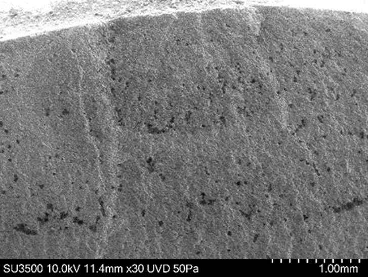
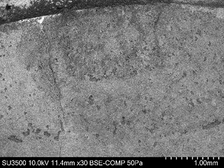
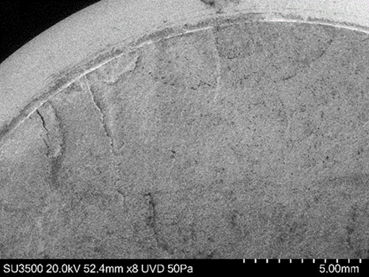
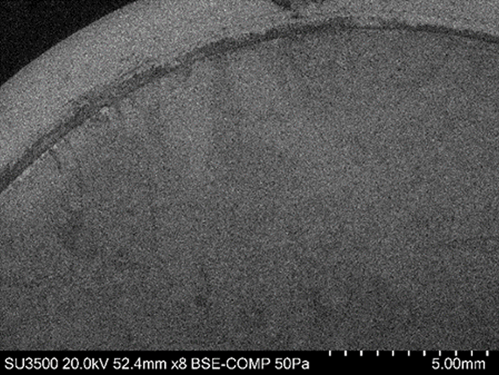
Fracture surface of the failed short shaft under low vacuum and secondary electron image.
Fracture surface of the failed short shaft under low vacuum and back scattered electron image.
Evidence of fatigue crack in the failed short shaft under low vacuum and secondary electron image.
Evidence of fatigue crack in the failed short shaft under low vacuum and secondary electron image.
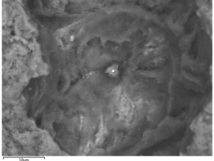
Back scattered electron image of an area of the fracture surface that includes an inclusion.
Energy dispersive X-ray spectrum from the inclusion shown in the image above indicating a high concentration of S and Mn.
Figure 4: EDS spectrum showing Mn and S inclusions.