Background
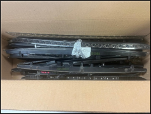
Two magnet retaining clip specimens (Figure 1) were submitted to CMH Metlabs by Unimotors (SMP Motor Products Ltd.). One specimen represents a failed clip, while the other is in good condition for comparison purposes.
The client has requested a comprehensive metallurgical evaluation of both specimens, including visual inspection, chemical composition analysis, hardness testing, and microscopic examination.
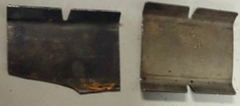
Figure 1. The magnet retaining clips, as received; a) Failed; b). Clip in good condition
Scope/Methodology:
This report covers the following aspects of the metallurgical failure investigation:
- Visual Inspection and Stereoscopic Examination
- Microscopic Examination (light microscopy) and microstructural analysis
- Testing Hardness/Evaluation
- Chemical Analysis through XRF spectrometer
- Discussion and Analysis
- Conclusions and Recommendations
Visual Inspection and Stereoscopic Examination
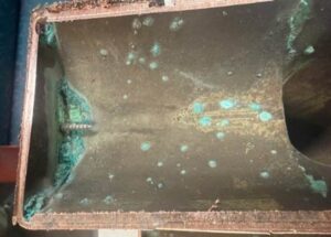
The failed clip was examined visually using a stereoscope (Figure 2). The following observations were made:
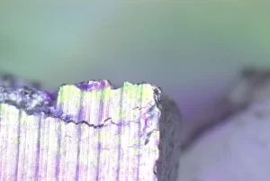
- The fracture surface exhibits characteristics consistent with brittle failure, as there is no noticeable reduction in thickness or evidence of plastic deformation in the region adjacent to the fracture.
- The failed component exhibited a blue tint on the surface, which is indicative of oxidation. This coloration suggests that the part may have been subjected to a post-heat treatment at relatively low temperatures followed by air cooling, resulting in the observed blue oxide film.
Stereo Microscope
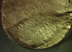
Stereoscopic examination of the fracture surface revealed the presence of cavity-like features, which are considered to have formed during the fracture process. The fracture surface exhibited a granular, crystalline morphology with no evidence of plastic deformation, such as necking or dimple rupture. These characteristics are indicative of a brittle fracture mode. The fracture is interpreted to have initiated at a region of stress concentration and propagated rapidly, consistent with a relatively high hardness and reduced toughness of the material.
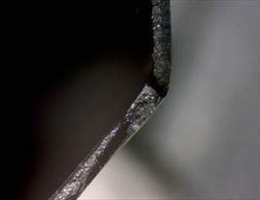
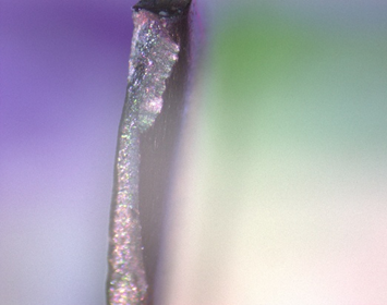
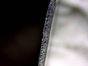
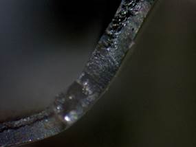
Figure 2. Fractographs of the failed clip taken through stereoscope.
Microscopic Examination/Light Microscopy
One sample from each of the failed and the good clip was sectioned, mounted in Bakelite, ground, polished, and examined using an optical microscope in both unetched and etched conditions. Representative photomicrographs are presented in Figures 3 and 4, respectively. The key observations are as follows:
i). No evidence of cracking or significant porosity was observed in the examined specimens.
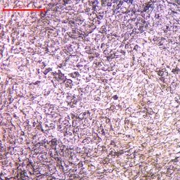
ii). The microstructure consists of very fine, needle-like features, indicative of a martensitic–bainitic structure with some widmanstatten ferrite, polygonal ferrite and retained austenite.
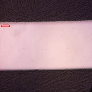
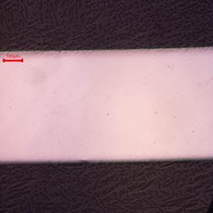
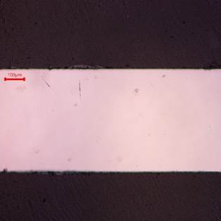
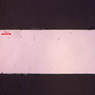
Figure 2. Photomicrographs of the clip samples in unetched condition revealed no evidence of cracking. Additionally, no significant porosity was observed in the specimens examined under the light microscope
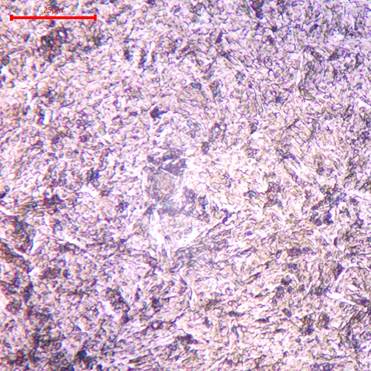
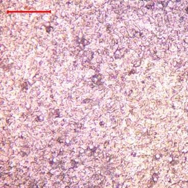
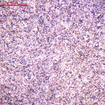
a). Failed Clip Material, Nital etched b). Clip in good condition, Nital etched
Figure 5. (a) Photomicrograph of the failed clip material, showing laths and featherlike features typical of bainitic microstructure and indicative of austenite transformation occurring around upper bainite temperature range. Widmanstatten ferrite and polygonal ferrite are evident and appear to be more in the failed clip material compared to the clip in good condition. (b) Photomicrograph of the clip material in good condition, exhibiting fine needlelike features indicative of lower bainite. Note that brighter features appear to be retained austenite in the clip representing good clip.
Hardness Testing
The mounted clip specimens were evaluated through a Vickers hardness tester using 0.2 Kg load, and 5 sec dwell time. The results are summarized in Table 1. Table 2 also include hardness in Rockwell scale C after conversion from the Vicker hardness data per ASTM E140. The data indicate a variation in hardness between the failed and the good clips, with the failed clip exhibiting relatively higher hardness. However, a variability is observed within the hardness measurements for each set of specimens.
Table 1. Clip Hardness Test Results, HV, 0.2kg, 5sec, 10x
| Condition | Test 1 | Test 2 | Test 3 | Test 4 | Test 5 | Test 6 | Test 7 | Mean | Standard Deviation | HRC (converted) |
| Good | 471 | 554 | 524 | 497 | 554 | 510 | 459 | 510 | 37 | ~50 |
| Failed | 776 | 803 | 727 | 682 | 704 | 727 | 704 | 732 | 43 | ~61 |
Chemical Analysis
Each clip was tested for chemical analysis using XRF spectrometer. The results are presented in Table 2. Note that manganese is higher and silicon is slightly lower in the material representing the clip in a good condition compared to the material representing the failed clip.
Table 2. Chemical analysis of the clip samples (XRF Spectrometry)
| Clip type | Fe | Mn | Co | Si | Cr | Cu | Ni | Ti | W | V | Ta | Sr | Mo | P | S | Nb |
| Good | 97.71 | 0.90 | 0.40 | 0.31 | 0.22 | 0.15 | 0.13 | 0.06 | 0.06 | 0.05 | 0.03 | 0.02 | 0.02 | 0.01 | 0.01 | 0.01 |
| Failed | 97.88 | 0.50 | 0.38 | 0.44 | 0.29 | 0.13 | 0.11 | 0.07 | 0.07 | 0.04 | 0.02 | 0.04 | 0.02 | 0.01 | NA | 0.01 |
Note that XRF spectrometer cannot analyses carbon and some other light elements.
Discussion and Analysis
Visual examination using a stereoscope of the failed clip specimens revealed the presence of microvoids. These voids are likely associated with the fracture process, as no pre-existing cracks or voids were observed in either the failed or clip in good condition (sound) specimens under unetched conditions during microstructural evaluation.
The fracture surface morphology suggests a brittle failure mode, as no appreciable plastic deformation was observed and the overall specimen thickness remained unchanged in the failed region.
Optical microscopy of the failed clip material indicates a microstructure composed predominantly of lath-like and feather-like features, consistent with a mixture of upper bainite and martensite. The presence of martensite is significant, as it is characteristically harder and more brittle. Furthermore, there appears to be higher content of Widmanstatten ferrite and polygonal ferrite in the material representing the failed clip that may have been generated due to lower manganese and the silicon relative to the clip in good condition. Widmanstatten ferrite and polygonal ferrite are believed to reduce toughness of steel. However, the available data do not establish a direct relationship between chemical composition and the observed failure.
In contrast, the material representing the good condition (sound) clip appears to exhibit a finer, needle-like microstructure typical of lower bainite and/or tempered martensite, which is generally associated with improved toughness and reduced brittleness.
Hardness measurements indicate that the failed clip material is harder than the good condition (sound) clip material. This increase in hardness is typically accompanied by a reduction in toughness, making the material more susceptible to brittle fracture under impact or service loading conditions.
X-ray fluorescence (XRF) analysis shows no significant compositional differences between the two materials, except for manganese and silicon content. The good condition (sound) clip material contains a slightly higher manganese level (0.90 wt%) compared to the failed clip (0.50 wt%).
Manganese is known to influence hardenability and microstructural development, including the stability of retained austenite, which may affect toughness. The higher manganese content observed in the sound clip may therefore be associated with comparatively improved toughness and resistance to service loading. In addition, variations in manganese and silicon content can influence the resulting microstructure, including the potential formation of acicular ferrite versus Widmanstätten or polygonal ferrite. These microstructural features are known to exhibit differing mechanical properties; however, the available data is not sufficient to establish a direct correlation between composition and the observed failure.
Conclusions
The clips in the failed and good conditions exhibit broadly similar chemical compositions, except for manganese content. The material from the clip in good condition contains approximately 0.9 wt% Mn, whereas the failed clip contains approximately 0.50 wt% Mn. Manganese is known to promote retained austenite, which can contribute to improved toughness.
- The material from the failed clip was found to exhibit significant higher hardness compared to the material from the clip in good condition. This elevated hardness indicates a comparatively more brittle material condition, which reduces the ability of the component to accommodate stress through plastic deformation. As a result, the failed clip would be more susceptible to crack initiation and rapid propagation under service loading conditions. The higher hardness is therefore considered a significant contributing factor to the observed failure.
- Microstructural examination of the failed clip revealed lath and feathery morphologies consistent with a mixture of upper bainite and martensite. In contrast, the clip in good condition exhibited a predominantly fine, needle-like microstructure, characteristic of lower bainite and/or tempered martensite. These differences suggest a variation in microstructural condition between the two batches, with the microstructure in the failed clip potentially associated with reduced toughness. This condition may have increased susceptibility to fracture under service or impact loading.
- Optical microscopy did not reveal any pre-existing cracks or significant porosity in either of the examined clip specimens.
- Stereoscopic examination of the fracture surface revealed void-like features, which are interpreted as having formed during the fracture process. No comparable features were observed in the prepared metallographic sections examined under optical microscopy, indicating that these voids were not pre-existing in the material.