Background
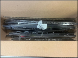
A wooden box containing eight pieces of failed threaded bolts, flange bearing housing, flange shaft, bearing and seal were received by CMH MET LABS. A photograph of the failed bolts is presented in Figure 1. In addition, some photographs of the equipment, drawings, materials specifications, inspection and installation reports were also received.
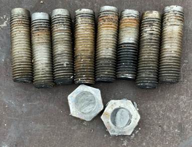
Figure 1. All M30x100 threaded bolts with shank failed at the base of the bolt heads in the shank (photograph provided by the client). No undamaged bolt was provided for examination. Length of the threaded region of the bolts approximately 90 mm, and the length of the shank attached to threaded part of the bolt ranges from 5 mm to 10 mm and total shank length could not be measured because the failures occurred in the shank towards the head side. The bolt heads, nuts and washers were not provided.
The bolts (part# 1041 per drawing of the lower bearing Figure 2) were used in the Lower Screw Pump (LSP-3); the LSP-3 is one of the several auger screw pumps that are employed at the wastewater treatment plant (WWTP) by the City of Lemington, Ontario.
We were informed that the through-holes in the bearing housing flange were unthreaded, while the through-holes in the bearing shaft flange exhibited minor thread imprint marks on some locations. The failed stainless steel bolts were specified as M30 × 100; however, one of the recovered bolts was measured to be approximately 90 mm in length.
Two bolt heads recovered from the job site displayed different manufacture markings, indicating that they were produced by two different manufacturers, although both were identified as the correct A4-70 stainless steel grade (Figures 3–4).
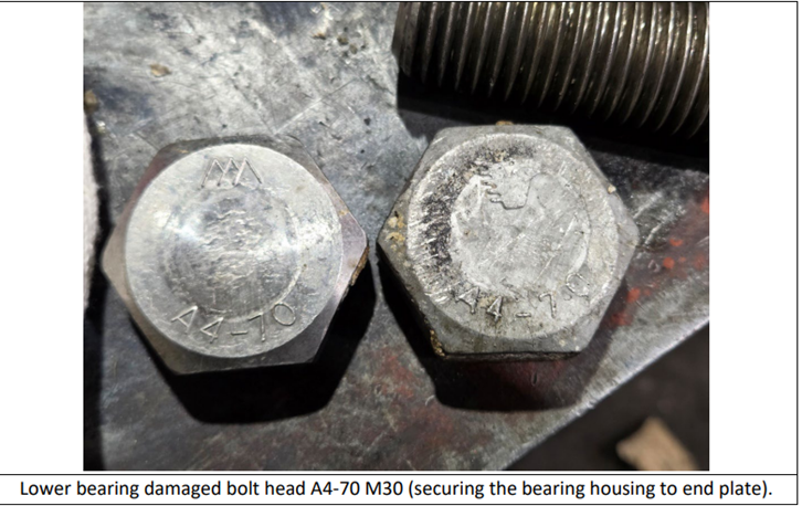
Figure 3. Bolt heads with markings (photo provided by the client).
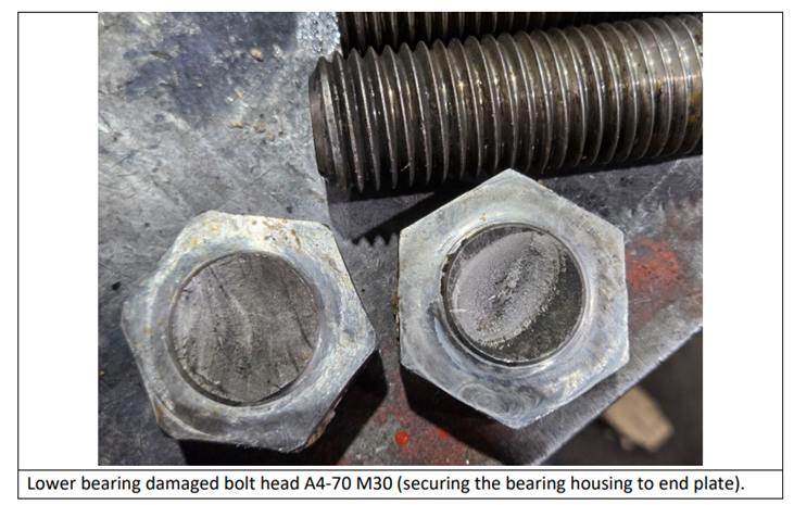
Figure 4. Bolt heads reveal the fracture surfaces of the bolt (Photo provided by the client).
The LSP-3 screw pump was in operation for about a year, prior to lower bearing failure. LSP 3 and LSP 2 M30x100 bolts with full threads were replaced by M30x100 with shank.
Additionally, we did not receive the washers associated with the failed bolts.
The client has asked us to perform metallurgical failure investigation. The investigation was performed by the following methodology/scope.
Scope/Methodology:
CMH MET LABS were asked to perform metallurgical examination of the failed bolts. This report covers the following aspects of the metallurgical failure investigation.
- Visual Inspection and Stereoscopic Examination
- Microscopic Examination (light and scanning electron microscopy) and microstructural analysis
- SEM/EDS Analysis
- Testing Hardness
- Chemical Analysis/Energy Dispersive Spectrometry
- Discussion and Analysis
- Conclusions and Recommendations
Visual Inspection and Stereoscopic Examination
The bolts, bearing housing, and bearing support were examined visually through unaided eyes and stereoscope. Following are the observations:
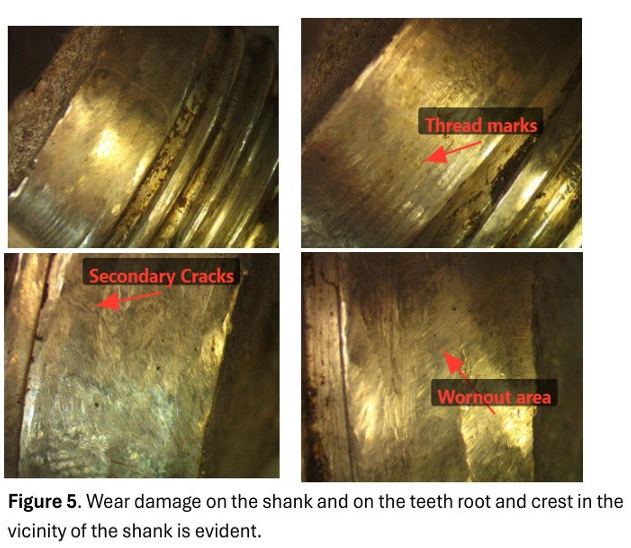
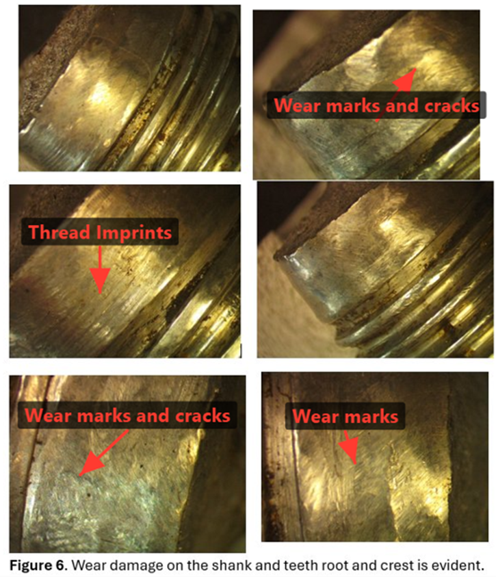
- All the bolts failed in the shank; when examined visually with unaided eye, the threads appear to have some damage but most of the threads were still intact (Fig. 1). Stereoscopic examination of the shank surface and the threads revealed wear damage (Figure 5-6).
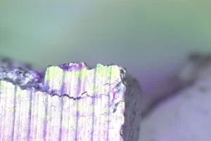
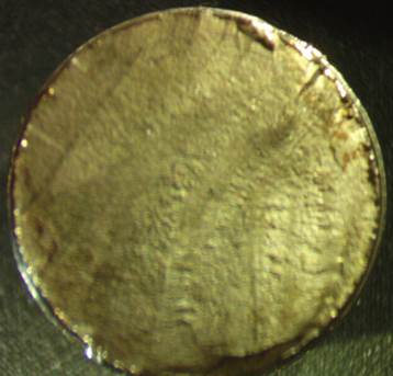
- There are beach marks, ratchet marks on the bolt fracture surface that are typical of fatigue failure mechanism (Figure 7-8).
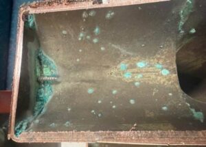
- Contaminants were observed in the bolt holes associated with bearing housing flange surface where the bolt heads sit. The contaminants appear to be solid waste and rust. The imprints of the bolt threads onto the inside surfaces of the holes of the flange were observed visually (Figure 9)
- There is sufficient clearance between the bolt segments and the bolt holes that allows easy sliding of the broken bolt segments (without heads) through the bolt holes.
| Ratchet Marks |
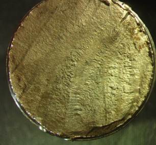
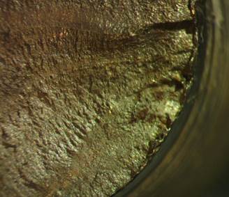
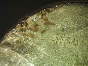
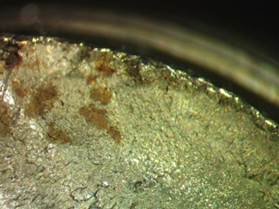
Figure 7 . Photograph of the bolt fracture surface showing beach marks, ratchet marks, characteristic of fatigue crack propagation. These features indicate progressive crack growth under cyclic loading, with multiple crack initiation sites visible on the fracture surface. The photographs were taken using a stereoscope.
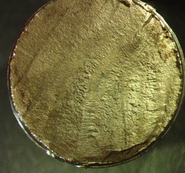
| Crack Initiation site |
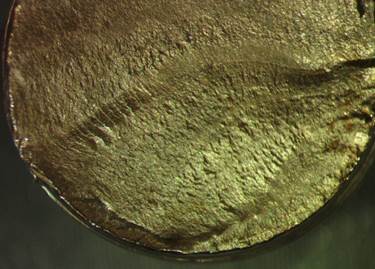

Figure 8. Photograph of the bolt fracture surface showing beach marks, ratchet marks, typical of fatigue crack propagation. These features indicate progressive crack growth under cyclic loading, with multiple crack initiation sites visible. The photograph was taken using a stereoscope.
| Thread imprints |
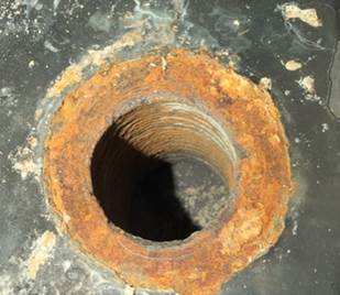
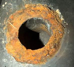
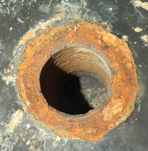
Figure 9. Thread imprints were observed on the bolt holes (part# 1041) associated with the bearing housing flange . The imprints suggest that the bolted connection has experienced vibration or cyclic loading or combination of both vibration and cyclic loading. This type of damage is often referred to as fretting wer/corrosion and may generate sites for the fatigue cracks.
Microscopic Examination
Two sections (axial and transverse) of randomly selected bolts were mounted in polymeric resin; ground and polished, and subsequently examined in an unetched condition, and then in electrolytically etched condition. Following are the key observations:
- There is no evidence of significant porosity or non-metallic inclusions in the steel bolt section in the unetched condition (Figure 10).
- There is no evidence of stress corrosion cracking.
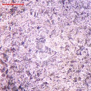
- Stringers parallel to x-axis observed in the microstructure (Figure 11-12) suggest that the bolt has been manufactured through cold working (cold rolling) process.
- Microstructure of electrolytically etched axial section consists of austenitic grain structure, annealing twins and slip bands (Figure 13), which suggest that the bolts have experienced thermomechanical processing, and the axial section in the vicinity of the teeth (Figure 14-15) indicates that the teeth have been manufactured through mechanical working (thread rolling). However, the microstructure away from the teeth consists of equiaxed austenitic grains.
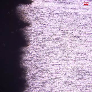
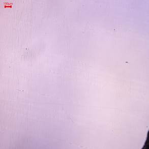
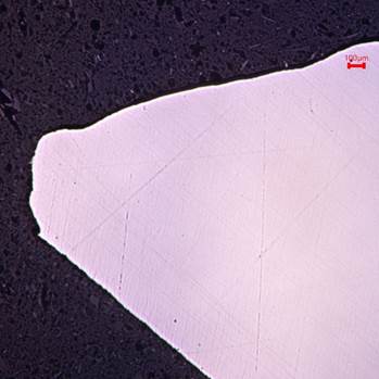
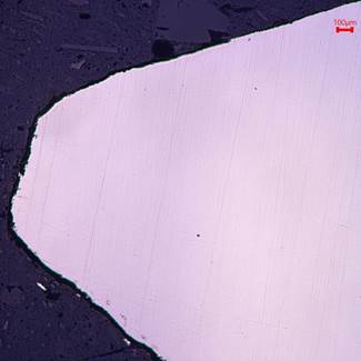

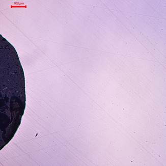
Figure 10 a. Axial section, unetched.
Figure 10b. Photomicrograph of the axial bolt section through the thread crest, thread root and shank. There is no evidence of porosity and cracks in the sections examined.
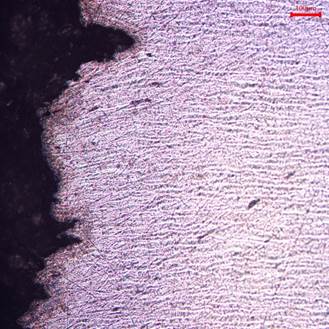
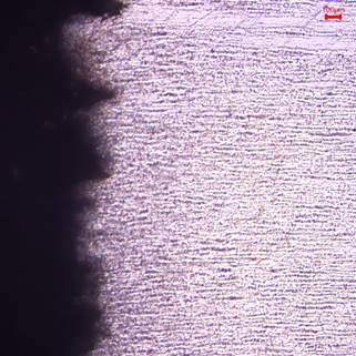
Figure 11. Axial section of the bolt; the photomicrographs show fibrous and jagged surface which indicates ductile fracture mode.
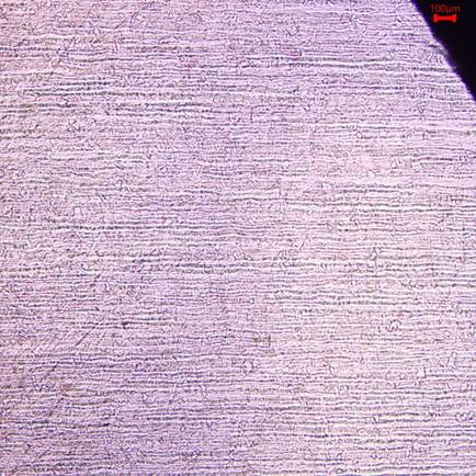
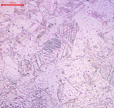
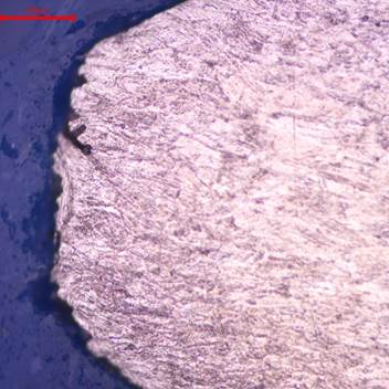
Figure 12. Axial section: stringers can be seen parallel to the axial direction, and suggest that the bolt has experienced cold working (cold rolling). The bolt section was electrolytically etched in oxalic acid solution.
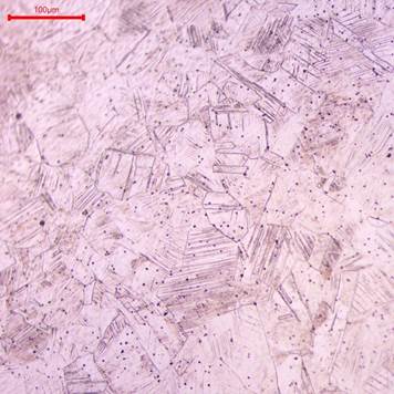
Figure 13. Microstructure of transverse section; equiaxed austenitic grain structure, annealing twins and slip bands are seen, which suggests that the bolts have experienced processing.

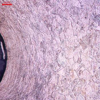
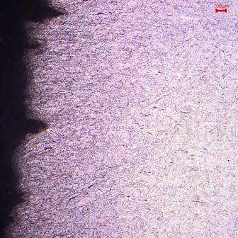
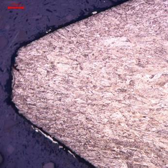
Figure 14. Axial section through the thread root (top row); and through the thread crest (bottom row); etched electrolytically in oxalic acid solution. Notice that grain flow pattern follows the contour of the thread and is indicative of thread rolling process. The crest of the thread (bottom row) appears to be truncated flat. Some damage to the crest is also evident.
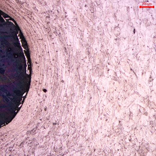
Figure 15. Photomicrograph of the axial section through the thread root; it is evident from the grain flow that the threads have been manufactured through thread rolling process. The microstructure of the region away from the threads reveals equiaxed grains. Annealing twins and slip bands are also evident.
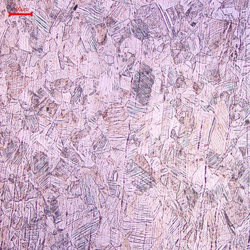
Figure 16. Photomicrograph of the axial section; austenitic grains, slip bands and annealing twins are seen. There are no chromium carbide precipitates along the austenite grain boundaries, and therefore, no intergranular cracks/attack is evident.
Scanning Electron Microscopy (SEM) and Energy Dispersive Spectrometry (EDS)
Fractographic examination and energy dispersive spectrometry (EDS) of one of the bolts was performed through scanning electron microscope (SEM) using secondary electron mode. SEM micrographs reveal striations that confirm fatigue associated with the bolt failure. Results are presented through Figures 17-20,and EDS spectrums are presented through Figures 21-22.
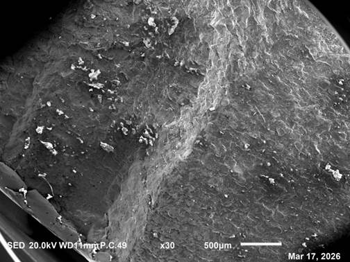
Figure 17. SEM photomicrograph taken through the edge near the crack initiation site of the bolt surface after fracture.
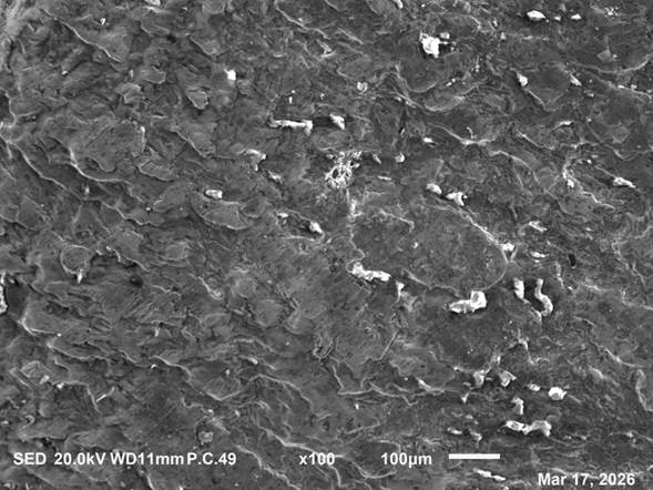
Figure 18. SEM photomicrograph taken through the edge of the bolt surface after fracture. Parabolic bands consisting of ridge-like features (parallel lines) referred to as striations are observed. Each striation suggests stress cycle. Parabolic bands suggest that failure most likely occurred due to cyclic shear loading.
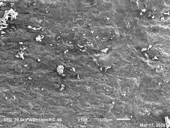
Figure 19. SEM photomicrograph taken through the edge of the bolt surface after fracture. Micro voids are evident.
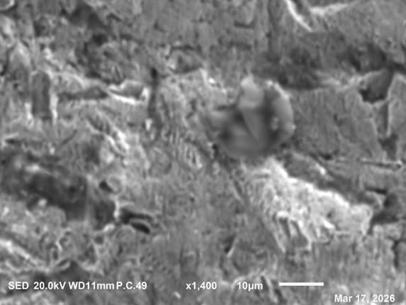
Figure 20. SEM photomicrograph taken through the center of the bolt surface after fracture. Striation bands and micro voids are evident.
Hardness Testing
Bolt section was tested for Rockwell hardness. Hardness data are presented in Table 1. Data reveals that there is no significant variation in the hardness relative to the location on the bolt section.
Table 2. The Bolt Hardness Test Results
| Test Type | Test 1 | Test 2 | Test 3 | Mean |
| Rockwell Hardness, HRC | 30 | 31 | 30 | 30.3 |
Discussion and Analysis
Fractographic examination of the failed bolts clearly indicates that fatigue was the dominant failure mechanism. However, additional potential mechanisms were evaluated to determine whether they may have contributed to the initiation of fatigue cracking. Possible mechanisms considered for the austenitic stainless-steel bolts included pitting corrosion, sensitization/intergranular corrosion, galvanic corrosion, fretting wear/corrosion, adhesive wear, and fatigue.
Pitting corrosion was considered but ruled out because no localized pitting or corrosion cavities were observed during microscopic analysis in the examined bolt sections in the unetched condition. Similarly, intergranular corrosion due to sensitization was also ruled out. Austenitic stainless steels may become susceptible to intergranular attack when exposed to temperatures in the range of approximately 600–850 °C, where chromium carbide precipitation may occur along grain boundaries. Metallographic examination of the bolts did not reveal chromium carbide precipitation or grain boundary attack, indicating that sensitization was not a contributing factor.
Corrosion was observed around the bolt seating area of the flange. This corrosion may be associated with galvanic interaction between the stainless-steel bolts and the carbon steel or grey cast iron flange in the presence of wastewater, where the flange material acts as the anodic component and becomes more susceptible to corrosion. Progressive corrosion around the bolt holes may result in localized material loss. However, the metallurgical evidence does not indicate that corrosion initiated the bolt fractures; therefore, it is considered a secondary contributing factor rather than the primary cause of failure.
Examination of the bearing housing revealed thread imprints along the inner surfaces of several bolt holes, indicating that the bolts experienced relative movement within the holes during service. Such damage is characteristic of fretting wear, which occurs when contacting surfaces undergo small-amplitude cyclic motion or vibration under load. Fretting damage can produce localized surface deterioration that acts as stress concentration sites for fatigue crack initiation.
Wear damage was also observed on the bolt shanks and thread regions, further indicating mechanical interaction between the bolt and surrounding joint components during operation. These observations suggest that the bolts likely experienced cyclic movement and localized contact stresses during service.
Fractographic examination of the fracture surfaces revealed beach marks, ratchet marks, and fatigue striations, which are characteristic features of fatigue crack propagation under cyclic loading. These features indicate that fatigue cracks initiated at localized surface damage sites—most likely associated with fretting wear—and subsequently propagated progressively across the bolt cross-section over numerous loading cycles before final overload fracture occurred.
The combined evidence of thread imprints within the bolt holes, wear on the bolt shanks, and corrosion around the hole surfaces suggests that the bolted joint may not have remained in a fully clamped, slip-resistant condition during service. Under such conditions, the bolts would experience not only tensile preload but also cyclic transverse shear and bending stresses, which significantly reduce fatigue life.
Based on the metallurgical examination and the observed service-related damage, the most probable failure mechanism involves fatigue crack initiation at wear-damaged regions of the bolt surface caused by fretting, followed by progressive fatigue crack propagation under cyclic service loading. Contributing factors may include vibration, joint loosening, or misalignment associated with the screw pump assembly, rather than an inherent metallurgical defect in the bolts.
Conclusion:
Based on the visual examination, stereoscopic fractography, SEM fractography, microstructural review, and hardness results, the failed M30 stainless steel bolts most likely failed by progressive fatigue under cyclic service loading rather than by a primary material defect or a corrosion-dominated cracking mechanism. The presence of beach marks, ratchet marks, and SEM-observed fatigue striations confirms repeated crack growth over many load cycles before final overload fracture.
The fatigue cracks appear to have initiated at or near the shank / thread transition and other locally damaged surface regions, where wear, fretting, and localized mechanical damage created stress raisers. The observed wear damage on the shank and threads, along with thread imprints in the bolt holes, indicates that the joint experienced relative movement, vibration, and/or insufficient clamping stability, all of which are consistent with fretting-assisted crack initiation. Once these surface discontinuities formed, cyclic loading during pump operation allowed the cracks to propagate progressively across the bolt cross-section until the remaining section could no longer sustain the applied load, resulting in final fracture.
The evidence does not support failure due to stress corrosion cracking, intergranular attack, significant pitting, porosity, or abnormal hardness variation. In addition, the report notes that galvanic effects at the flange may have contributed indirectly by promoting deterioration of the surrounding hole surfaces and increasing looseness or movement in the joint, but the dominant failure mode remains mechanically driven fatigue, most likely initiated by fretting/wear damage under vibration or cyclic misalignment-related loading.